Engineering diagrams
are vital for understanding of a process to chemical engineers, of equipment’s to mechanical engineers, of electrical circuits to electrical engineers and so on. These diagrams are prepared in many different ways to suit the specific requirements. Process flow diagrams (PFD) are basic requirements of process engineering and are prepared before attempting any detailing.Block Flow Diagram:
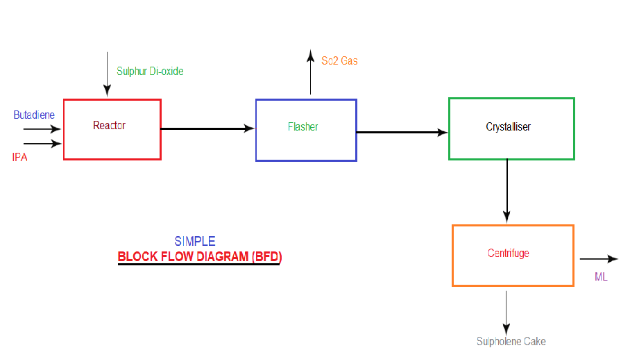
Block flow diagram drawing basically shows only the major process units and process flows (as illustrated in the figure). It help's in understanding the entire chemical process. A complete process plant can be shown in a single drawing. Typically, each unit operation is shown as a rectangle (block), and the blocks are connected by lines with the flow direction indicated with arrows. No special symbols or guidelines are used in developing Block flow diagram. .
A Block flow diagram (BFD) typically represents the following:
• Unit Operations/equipment are represented with blocks generally rectangular.
• Material flows are represented with straight lines with arrows giving the direction of material/process flow.
• Light streams (gases) are typically shown from the top of the block whereas heavy streams (liquids or solids) from the bottom of the block.
• Wherever more than one line leaves equipment, then each line should be clearly marked.
• Lines between the unit operations/equipment are horizontal or vertical, with turns at 90 degree angles, etc.